Abstract
Corrosion under insulation (CUI) is a common cause of pipeline failure in the oil and gas industry. Its detection with conventional inspection techniques is challenging due to the presence of the insulation layer and a protective metallic cladding that prevent direct access to the pipe surface. This paper presents a new guided microwave technology that offers a cost-effective approach to screen the insulation layer for the presence of water – a necessary precursor for CUI.
CUI Mechanism
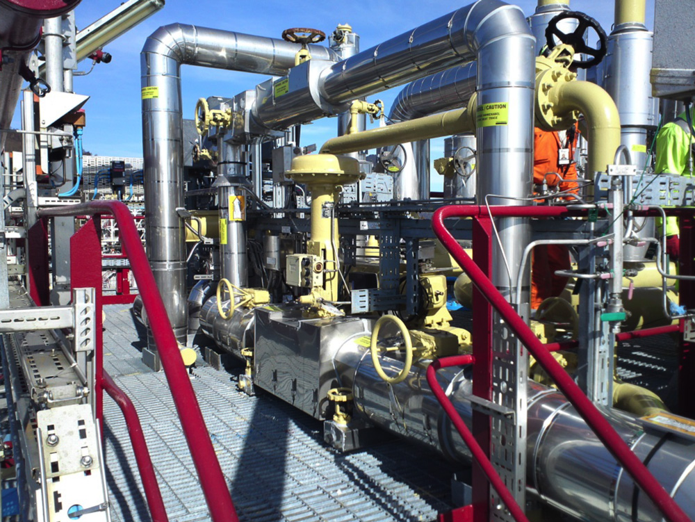
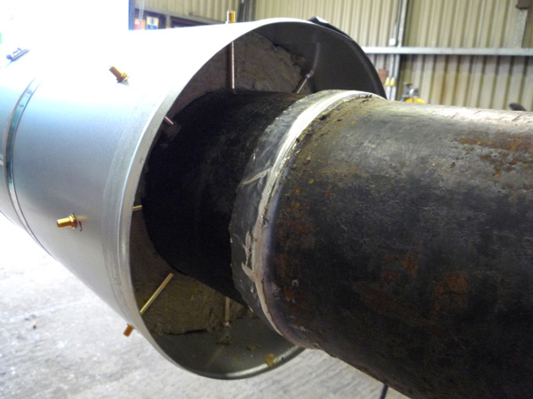
Picture courtesy of Beerenberg Corp. AS
Often during operation the metallic cladding that protects the insulation of pipelines forms gaps that expose the insulation to water and allow it to accumulate around the pipe. This causes the initiation of corrosion which can progress at high rates when the pipe is subject to significant thermal cycles or when contaminants are present in the water e.g. salt or acids. This leads to the problem of Corrosion Under Insulation or CUI.
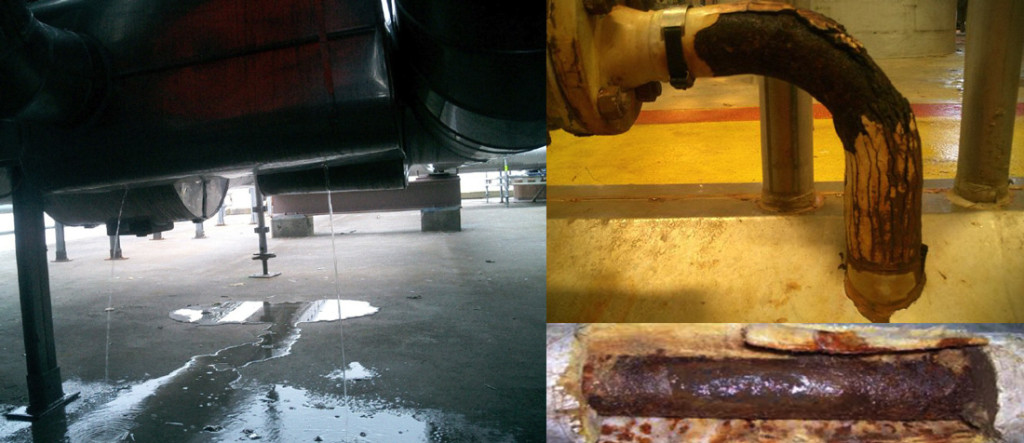
CUI is Expensive – Picture courtesy of Beerenberg Corp. AS
Detection of CUI with conventional NDE methods is challenging as there is no direct access to the pipe surface and removal of the the insulation and cladding are prohibitively expensive. The various approaches that are currently being investigates can be grouped in two broad categories: 1) direct methods that attempt to detect corrosion damage; and 2) indirect methods aimed at detecting water inside the insulation which is the precursor for CUI.
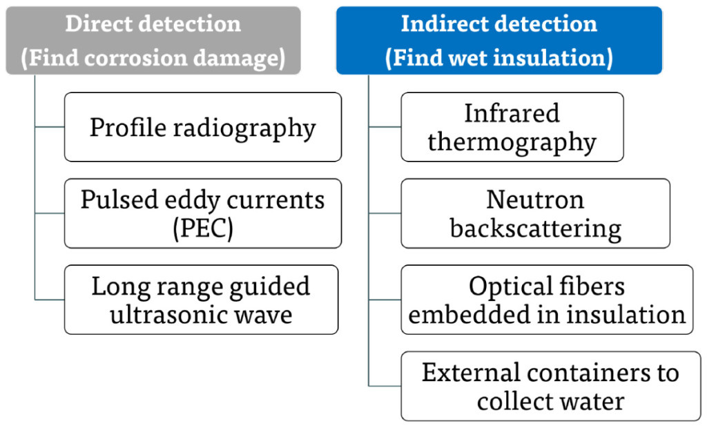
Approaches to CUI Detection
Guided Microwave: The Principle
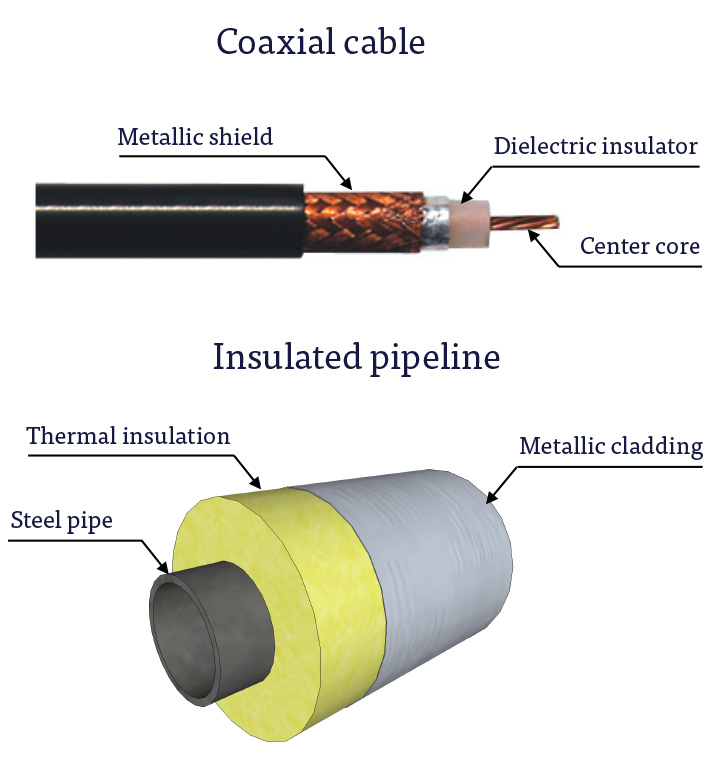
The electrically conductive pipe and cladding form a coaxial waveguide with the thermal insulation acting as a dielectric. Electromagnetic signals can therefore propagate along the pipe inside the insulation in a similar way as the signals transmitted by a coaxial cable. Microwave signals are chosen as they are highly sensitive to water and reflect from wet insulation.
An array of antennas is used to launch a microwave pulse inside the insulation. The same array detects pulse reflections from wet insulation sections. Timing the pulse journey enables accurate location of wet insulation.
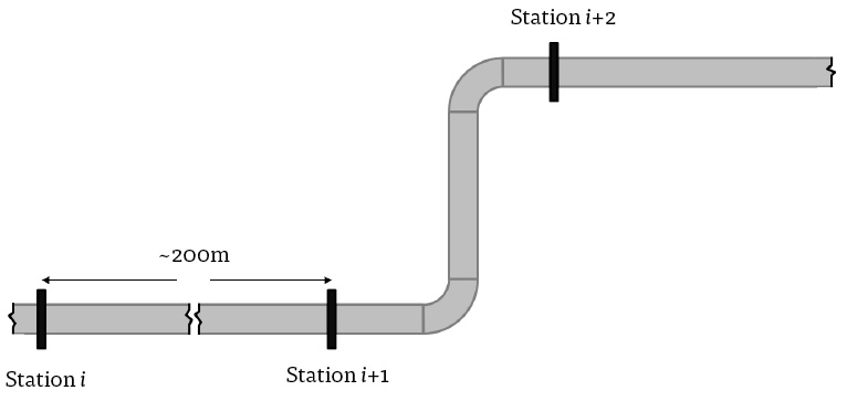
MW Monitoring Concept
We use a distributed network of inspection stations each containing a permanently installed antenna array. The distance between stations depends on insulation type and could be up to 200 m. Stations can be accessed directly with portable instruments or remotely using permanently installed electronics.
Portable Electronics Battery powered portable instruments are ruggedized for field testing. An inspector plugs the instrument into a station port and acquires the signal in a few seconds. He/she then moves to the next station and repeats the measurement.
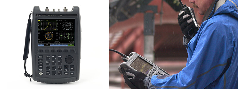
Portable Electronics – Reproduced with Permission, Courtesy of Keysight Technologies, Inc.
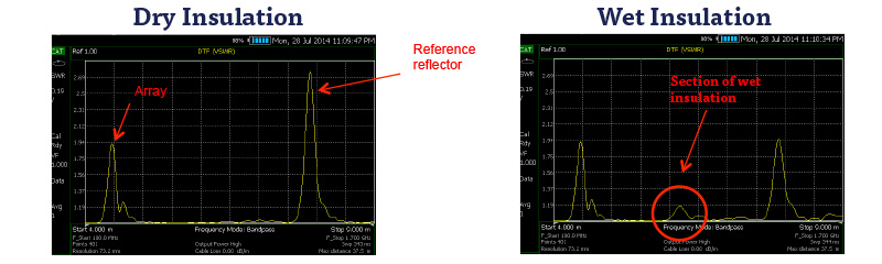
Echograms show the position of reflectors as a function of distance from the inspection station in real time. The neighboring station provides a reference reflector for signal quality control. Wet insulation appears as a new reflector in the echograms with the amplitude of the reflection being indicative of the water volume.
Sensitivity and Inspection Range
Sensitivity depends on signal strength relative to background coherent noise.
Key factors in signal strength
- Water volume size and morphology
- Inspection range
- Type of insulation
- Bends
- Supports
Sources of background noise
- Non-optimal antenna design
- Presence of discontinuities in the waveguide
- Bends
- Supports
- Major dents in the cladding
Reflectivity from Wet Insulation
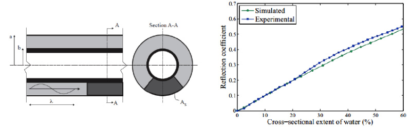
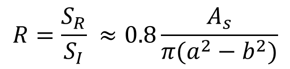
The strength of the reflection is quantified by the reflection coefficient R which is the ratio between the amplitudes of the reflected, SR, and incident, SI, signals. For wet insulation with a planar saturation front orthogonal to the incident signal, R is given by
Effect of saturation gradients
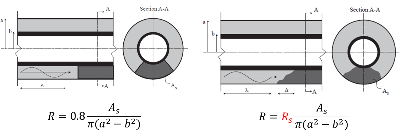
Saturation fronts are typically irregular and the transition from dry to wet insulation can be gradual leading to a saturation gradient. These effects can weaken the strength of the reflection even if the cross-sectional area remains the same. The weaker reflectivity is represented by the factor 
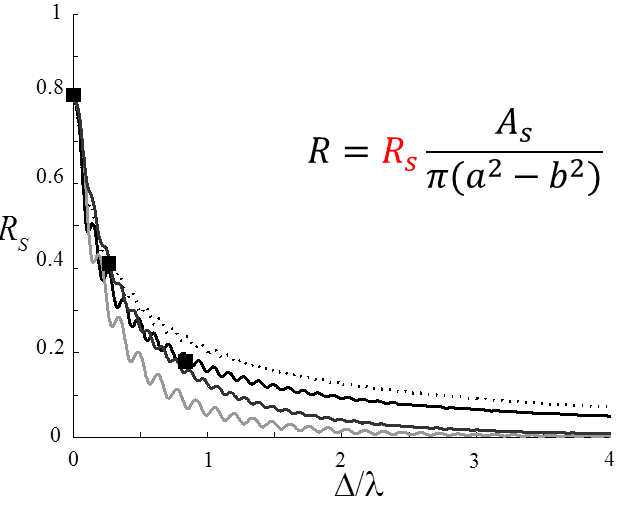
The inhomogeneity of the saturation front is captured by the length scale  , relative of the wavelength of the incident signal,
  . When
  ,
,  is independent of the shape of the saturation front with a lower bound of ~0.4. Our technology employs a wavelength that is about 4 times the insulation thickness, therefore the saturation front has a significant effect on reflectivity only when it extends over a scale greater than the insulation thickness.
Monitoring Results
The examples below show how the proposed technique is capable of detecting small volumes of water and characterize the dynamics of water capillary rise and seepage over a range of time scales.
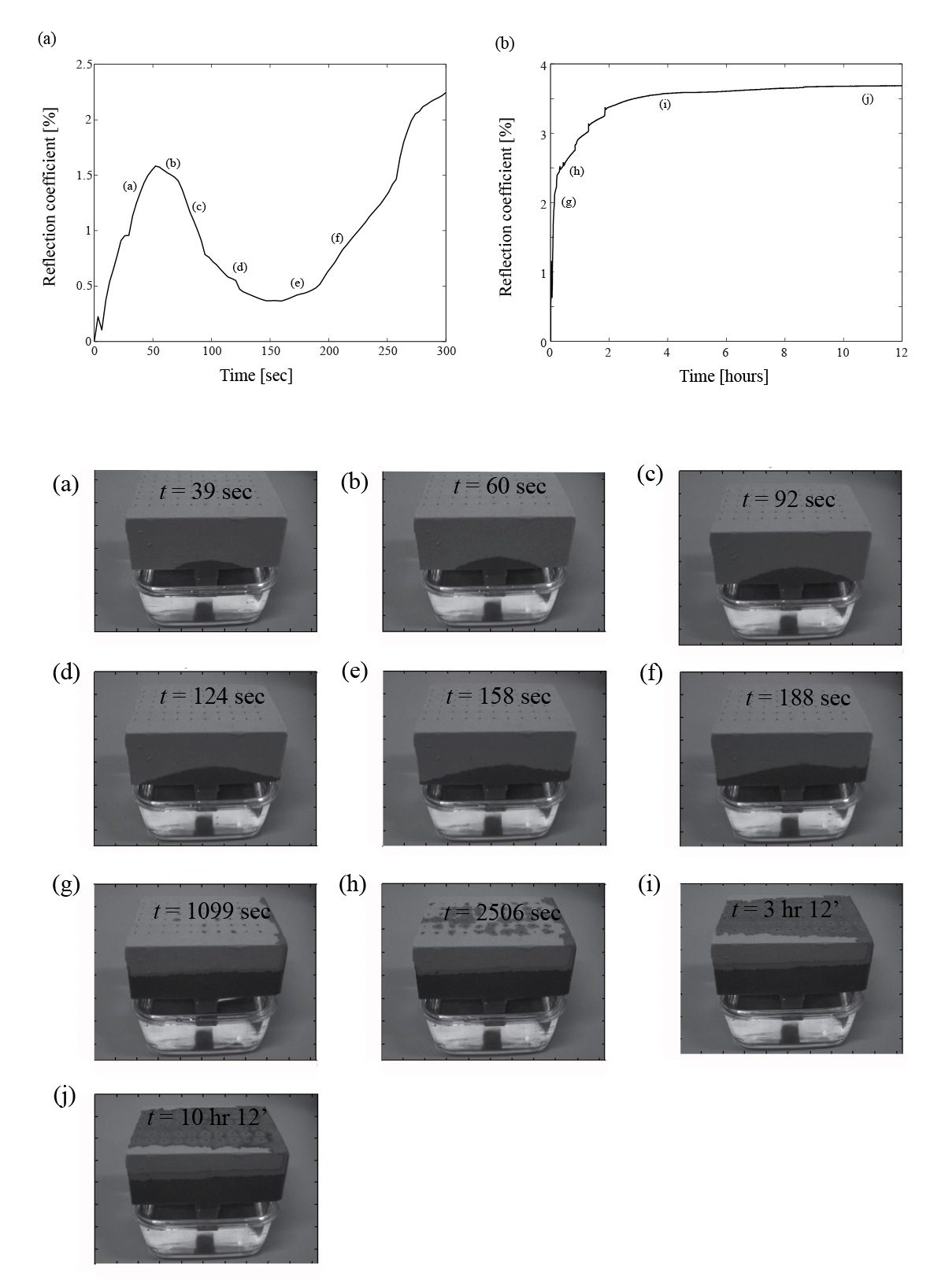
Saturation Fronts due to Capillary Rise
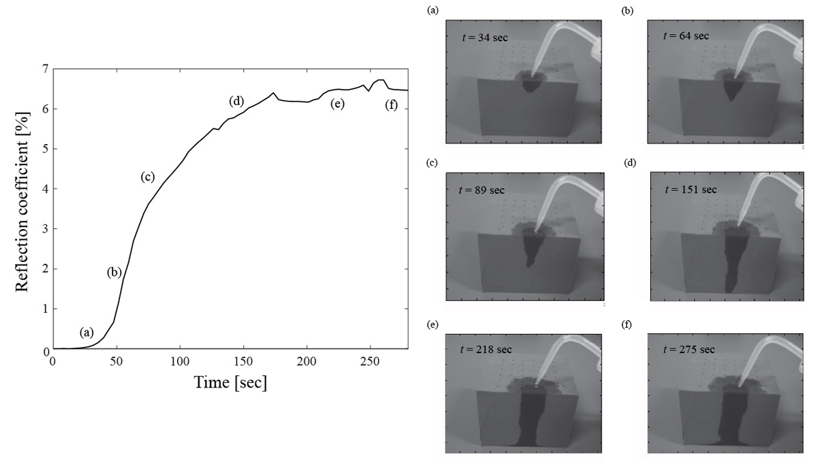
Saturation Fronts due to Seepage
Effect of Insulation Material
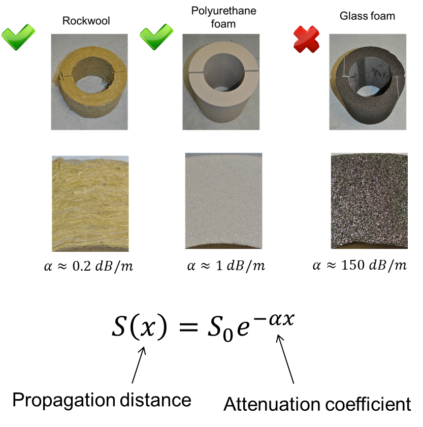
Signal amplitude decays with propagation distance due to energy loss inside the insulation. The decay is characterized by the pulse-echo attenuation coefficient  which depends on the type of insulation material. Since the signal decay should not exceed 40dB, the maximum inspection range, L, can be obtained as


Conclusions
- Guided microwave technology is a cost-effective solution for the detection of water in the thermal insulation of pipelines
- The technique provides rapid, full-volume, inspection of the insulation annulus
- Most types of insulation materials are essentially transparent to microwave thus ensuring long inspection range
- Long-range inspection capability is also possible in the presence of pipe supports and bends
- Highly sensitive to small water volumes down to 5% of insulation annulus cross-sectional area
Additional information about the technology can be found in:
- S.M. Vejjavarapu and F. Simonetti. An experimental model for guided microwave backscattering from wet insulation in pipelines, J. Nondestructive Evaluation, 33, 583-596, 2014.
- R. E. Jones, F. Simonetti, M.J.S. Lowe, I.P. Bradley. The effect of Bends on the long-range microwave inspection of thermally insulated pipelines for the detection of water J. Nondestructive Evaluation, 31, 117-127, 2012.
- R. E. Jones, F. Simonetti, M.J.S. Lowe, I.P. Bradley. Use of microwaves for the detection of water as a cause of corrosion under insulation J. Nondestructive Evaluation, 31, 65-76, 2012.